Computer Vision for Robotics 🦆🦆🦆
I improve localization of the robot in the environment using static landmarks.
Contributors
Leen Alzebdeh and Tianming Han
Summary
In this exercise, we managed to write a ROS container that is able to continuously relocalize the robot while utilizing the dead reckoning node to provide an up-to-date measurement of the robot position.
Objective
Our objective is to visualize robot transforms by using a fixed world frame and considering all other frames, including the robot frame, relative to it. We aim to improve localization of the robot in the environment by using static landmarks, AprilTags, in the environment. We also aim to incorporate computer vision for the robot to drive inside road lanes, and to detect the ID of each AprilTag it observes in the environment.
Background
In the last exercise, our robot was able to locate itself according to its initial position and drive autonomously according to preset motions. We had also used the led_emitter topic to convey the state of the robot through light patterns. Driving relative to the initial position creates limitations to the robot’s knowledge of where it is and how far it has travelled and this motivates the use of global coordinates for the frame.
Methods and Results
Task 1- Computer Vision: https://github.com/CMPUT412-Exercise2-Leen-Tianming/AdvancedARExercise
We start by writing a node that subscribes to the hostname/camera_node/image/compressed topic. To reduce the effect of lens distortion, we undisort the image we receive by first importing intrinsic and extrinsic camera values, from which we extract the camera matrix, used to convert from 3D camera to 2D image coordinates, and the distortion coefficients, which describes distortions in the image. Using OpenCV’s cv2.getOptimalNewCameraMatrix, we obtain a new camera matrix which we use to obtain a new undistorted image, using cv2.undistort, which we publish to the topic hostname/compressed.
We additionally use the Detector class from the library dt_AprilTags to detect tags that appear in the image, and extract their translation and corners, which we use to mark the center and edges of the tags in the published image, along with the name corresponding to each tag’s ID.
In addition to marking the tags in the published image, we reflect this detection through different color in the LEDs, which we do using the LEDClient class that utilizes the hostname/led_emitter_node/set_pattern service.
Task 2 - Lane Following: https://github.com/KarlHanEdn/E3P3Transform/tree/master/packages/lane_following
To start, we first create a node which can stay inside a lane, we first subscribe to the image topic. On the incoming stream, using OpenCV, we apply color masking to capture the yellow lane markings, apply enough dilation so the yellow marking blobs form a bigger blob, and find the contour with the largest area.
In order to determine the direction the Duckiebot is travelling, we calculates the center of the contour by taking the bounding box of the contour and computing its center. The center of the contour is expected to lie on a line that is static if the robot is driving right in the middle. To adjust position, we measure the difference between the reference line and actual line through the contour as follows:
position_ref = -position_line_ref[2].item() - contour_y * position_line_ref[1].item() position_error = position_ref - contour_xWhere position_ref is the expected x location on the line we want the yellow lane marks to lie on, while the equation on the right calculates it by using a line equation that we manually selected from a reference image when the robot is right in the middle of the left lane.
And similarly, to determine if our angle needs to be adjusted, we calculate the error using:
angle_error = (ref_angle - angle + math.pi) % (2 * math.pi) - math.Where ref_angle is the angle of the reference line.
To better regulate the robot’s motion, we implemented a PID controller, where we start by publishing the velocity of the left and right wheels to the hostname/wheels_driver_node/wheels_cmd topic for debugging. We then calculates the error integral and derivative by summing up/subtracting between consecutive observed errors. With the error as well as its integral/derivative, we multiple the three terms by three tunable coefficients and sum them up to get the direction and magnitude of the turn. To make the turn, we just add/subtract a number from the speeds of left and right wheels. The results of our duckiebot drives in the English style are shown below.
Task 3 - Localization using Sensor Fusion
To localize the robot in 3d, we need a way to calculate the transformations from observed landmarks to our robot positions and convert that in the world frame. These can be managed in ROS via the tf/tf2 library. They can publish known positions and provide lookup to transformations between existing frames. Due to the difficulty of judging if the position estimate is accurate in 3d, we also need RViz, which is a tool to provide 3d visualization for the robot.
First we modeled the landmarks by using the measured positions provided by our TA, along with their orientations (which way it faces). We broadcasted their 3d poses when the AprilTag detector node boots up, with the orientation transformed to match the one used by dt-AprilTag library (which has the AprilTag facing z- direction in its own frame) and their height is set to 0.1 meters from the ground. We use a dictionary with AprilTag ids as keys and we are able to lookup corresponding locations by querying the frame with the name "tag<id>".
For the first step in localization (3.1 and 3.2) we simply initialize our robot odometry at a fixed location on the duckietown, facing x+ axis with the orientation represented as the unit quaternion (0, 0, 0, 1). The initialization is done by broadcasting a TransformStamped message to a separate topic. Our dead reckoning node listens to that topic and records the transformations and calculates position offsets from wheel encoder data on top of that.
RViz, rqt_image_view and other useful small programs like rostopic or rosnode can be launched inside start_gui_tools. We launched gui tools and rviz. After recording a video of the visualized result of the duckiebot driving a circle around the duckietown, we were sure the transform was working and moved on to the next part.
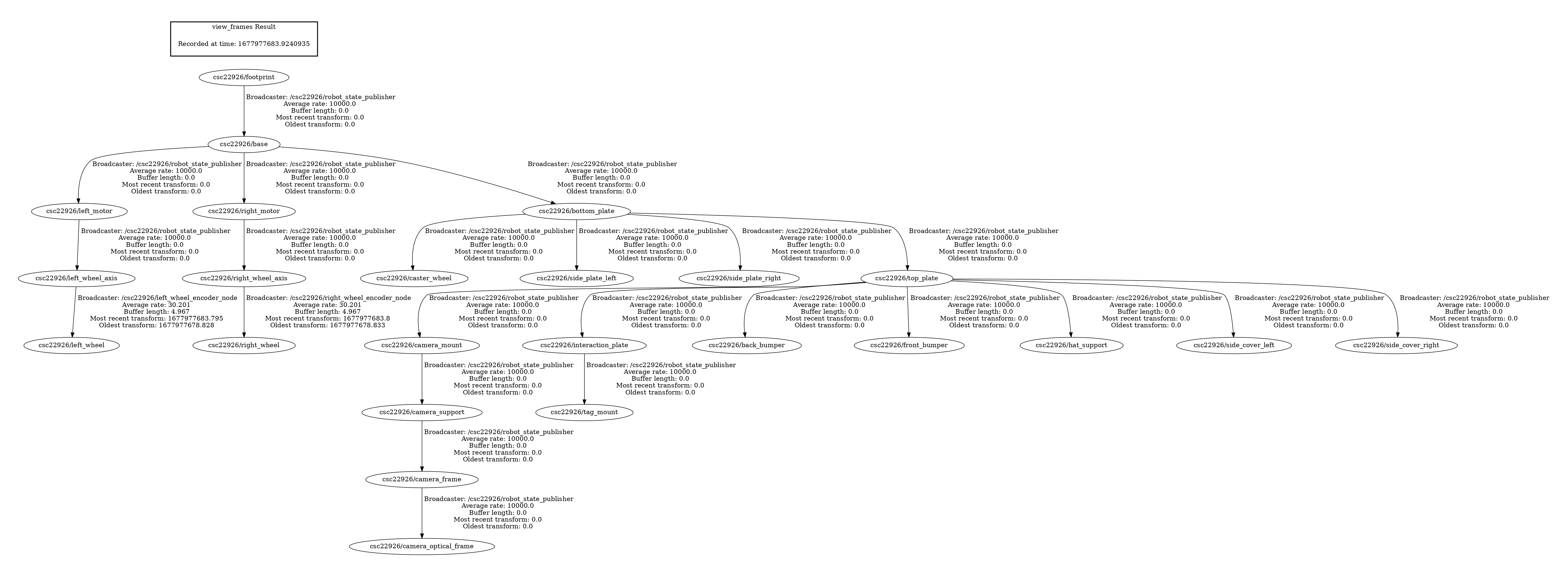
For 3.3 the transform graph is generated by tf2_tools. In order to get access to the tools we log onto the ROS container on the robot through the console option of the portainer. Afterwards we use “rosrun tf2_tools view_frames.py” to run the tools and view the result after using scp to transmit it back to our laptop. In the graph we see all component frames of the robot listed as nodes, with the $veh/footprint node at the top as root frame for all nodes.
We also used RViz to visualize the robot frames. After adding the tf visualization and the robot model into the scene, we were able to see the robot’s camera, top plate, base and wheel axis positions are all modeled by the component frames. When rotating the robot wheels, we notice one frame at the left/right wheel location rotates, which is the $veh/left_wheel frame.
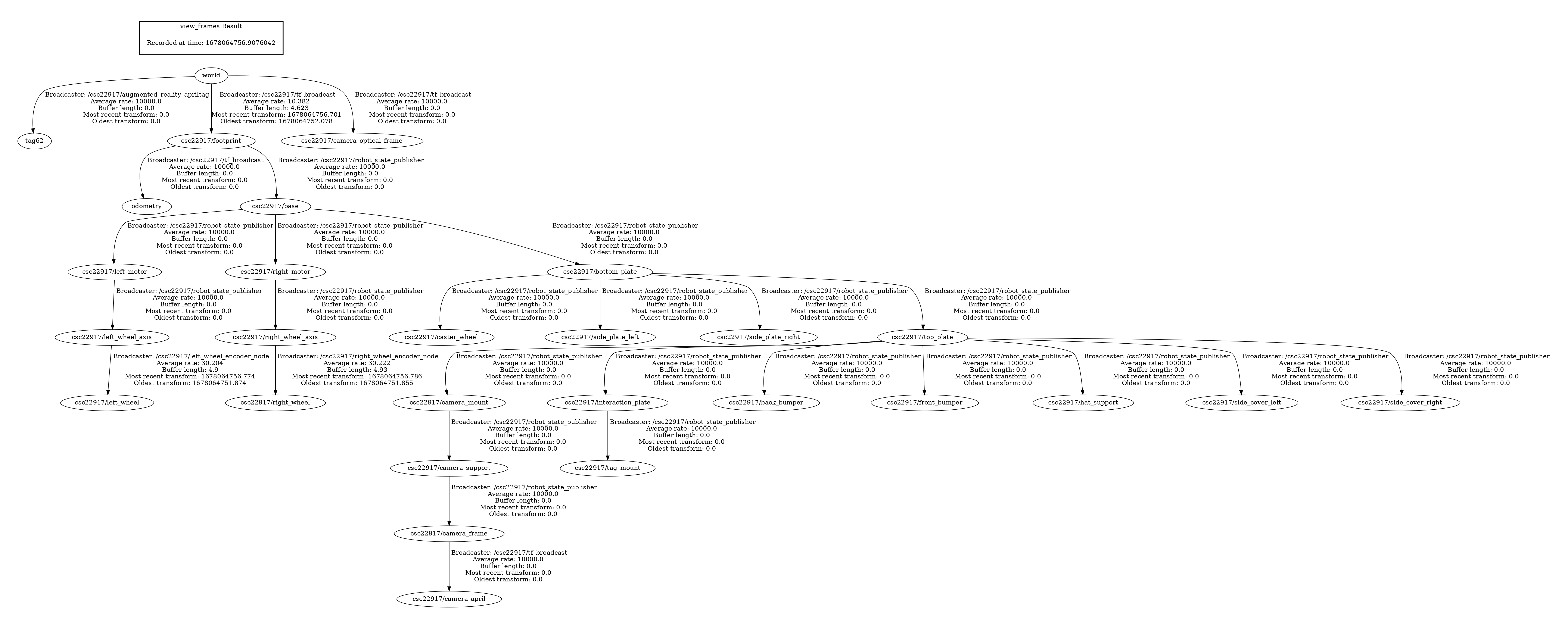
For 3.5, we need to connect the robot frames to our odometry estimation. We broadcasted the footprint frame as the parent and odometry estimation as child to a StaticTransformationBroadcaster via tf package. Then after remaking the transform graph we see odometry as a child of the footprint frame. The root frame is still the footprint frame (ignoring the world frame at the top) because we have not broadcasted any frame as parent of the footprint frame.
For 3.6, we need to detect AprilTags and use our robot’s dead reckoning estimate to estimate the position of the AprilTag it sees. With the static AprilTag visualizations setup in 3.2, we can compare between the estimation and the ground truths. The AprilTag detections return both a translation pose_t and a rotation matrix pose_R, which transforms from the dt-AprilTag’s camera frame and the AprilTag frame. With this transformation we can estimate the tags’ position by attaching a child frame on the camera AprilTag’s frame with the pose_t and pose_R transformation and publish it using tf. Then the automatic transform calculation allow use to see the tags’ estimated positions in RViz. Driving around the duckietown, we see that the tags’ orientations are estimated relatively accurately by the robot, but their positions become very inaccurate as the robot’s dead reckoning gradually becomes unreliable.
In 3.7 we localize our robot using camera AprilTag observations. Similar to 3.6, but this time we correct for the world->base_link transformation instead of the camera->tag transformation every time we see an AprilTag, and we utilize the localization initialization topic we created in 3.2. Now we know three transformations: world->tag given by the map of landmarks, /footprint->camera given by the tf graph and camera->tag given by the AprilTag detection topic. We can chain them together to obtain the world->/footprint transformation which is what we look for. Now each time the AprilTag is seen in the camera, we update our robot’s footprint frame position and display it in the RViz, as shown in the video below.
QAs
1.2 AprilTag Node
What does the AprilTag library return to you for determining its position?
A list of detections is returned for an input camera image, each detection has a pose_t attribute that contains the (x, y, z) offset of AprilTag in relation to the duckiebot’s camera position.
Which directions do the X, Y, Z values of your detection increase/decrease
X increases as the tag moves right (in the camera image), Y increases as the tag moves down, and Z increases as the tag moves away from the camera.
What frame orientation does the April tag use?
The AprilTag frame used by the dt-AprilTag library has the back of the tag facing z+ axis. When the camera is direction opposed to the AprilTag, the right side of the image is in the x+ axis and the down side of the image is in the y+ axis. The center of the three axes (origin) is the center of the AprilTag pattern.
Why are detections from far away prone to error?
Far-away detections are blurry in the image and their detected position contain more uncertainty. Numerically the length on an object in the image is inverse to its distance from the image, so by estimating the position from the shape and size of the AprilTag in terms of # of pixels N in the image, the uncertainty on the distance d is proportional to
1/(N - 1) - 1/N ≈ 1/N2 ∝ d2
So we get an uncertainty on the depth that is about quadratic to the real depth of the object.
Why may you want to limit the rate of detections?
It could lead to significant burden on the CPU as image detection is costly to run in real-time.
2 Lane Following
With a basic proportional controller, how well does it work? What happens when your control loop has a very large error?
A basic proportional controller does seem to keep the vehicle in lane, but in most cases it oscillates in its moving direction and goes off the lane eventually. When the control loop has a very large error, the vehicle will overshoot when trying to correct it, leading to an error of about equal magnitude (sometimes more) on the other side.
Try adding a derivative term, does that help? Why or why not? Does it help when the error is large?
The derivative term does not seem to help when we tested it.
When visualizing the error in a graph, we see that the derivative of the error is noisy and occasionally spikes up or down, which could be partly caused by the way we calculate the error, which involves selecting the largest group of yellow lane markers in the image, and when we jumps from one group to the next we get a large derivative term.
The derivative term does not help when the error is large.
Try adding an integral term, does that help? Is the I term useful? Why or why not?
An integral term does seem to help. In the case that the robot tends to move to one direction, the I term will grow in that direction and correct for the tendency until the robot stays in the middle of the lane. In a few runs that we did for both P and PI controllers, the oscillation also seemed to be less severe for PI controllers (and we got it running for multiple loops without failure), but the cause is unknown and we could not replicate it in a simple PID simulation in 1d motion control.
What is the error for your PID controller?
The error is the horizontal position difference in pixels between the center of the group of yellow lane markers and the expected lane position at the same height assuming the robot is in the middle of the lane. By minimizing this error we can make sure we stay in the middle of our lane.
What is the reason the proportional controller works badly (if it did)?
The P controller always overshoots when correcting large error, because it does not attempt to stop the momentum when the error approaches zero.
3.2 Creating Static Landmark Frames
Where does the odometry drift the most? Why?
The odometry estimation drifts the most at the end of the task after the robot has made many turns. In each turn we have less and less accurate estimates of its orientation because the wheel encoders are not as good at estimating orientation as it is at estimating distances traveled. Then as the robot moves forward with inaccurate orientation, its position becomes inaccurate as well.
Did adding landmarks make it easier to understand where the drifting occurred?
Yes, the landmarks help providing reference for the robot position, and we can see that the position becomes further away from its actual position as time passes.
3.4 Visualizing the Robot Transformations
What joint appears to be moving in the rviz when the robot wheels are rotating? What type of joint is this?
The joint “$veh_left_wheel_axis_to_left_wheel” appears to be rotating around the wheel axis as the robot moves. Looking at the URDF file, the type of the joint is continuous (as opposed to, for example, fixed joint type).
3.5 Connecting our Odometry Frame To Our Robot Frame
Why does the odometry frame move but the robot frame doesn’t?
rviz relies on finding a path in the tf tree from the fixed frame (which is the world frame) as the root frame of the environment to the robot frame in order to determine the transformation between the fixed frame and the robot. The robot root frame $veh/footprint is initially not linked to the odometry frame, and even after it is linked to the fixed frame its position will still not be affected by the movement of odometry because the path from the fixed frame to the robot frame does not contain the odometry frame.
3.6 Visualizing AprilTag Detections in RViz
How far off are Detections from April Tags’ True Positions?
April tags’ estimated positions are a few tens of centimeters away from their labeled positions in rviz, and increases as the robot continues to move.
What are two possible causes for this error?
One cause is from the errors in the dead-reckoning i.e. the delay and measurement errors from wheel encoder data. Another error comes from the AprilTag localization.
3.7 Calculating Transform from AprilTag to Robot Base & Applying to Static Frame
Is the resulting localization system perfect?
The resulting localization system is not perfect, because there are still errors from both dead reckoning algorithm and AprilTag detection algorithm. We also introduced occasional teleportation of the robot as one thing we need to take into account.
What are the causes of errors in this localization method?
For this method, both the errors from the dead-reckoning algorithm and ones from the AprilTag detection algorithm will end up affecting the results of localization.
Both wheel encoder and the camera suffers more or less from topic communication delays and observation errors due to imperfect sensors. For wheel encoders, slippery road may cause issues, and the errors from the wheel encoder is typically amplified when the robot is turning. For the AprilTag localization, we may get camera calibration errors or errors in the dt-AprilTags library’s detection algorithm.
What approaches could be used to improve localization?
One approach to improve localization may be to use methods that will increase the time period when the robot can use AprilTags localization and minimize the
use of dead-reckoning. We can try using existing SLAM algorithms. If the robot is outdoors then we can use GPS to locate it.
References
dt-AprilTags repository README.md: https://github.com/duckietown/lib-dt-AprilTags
color masking: [https://www.tutorialspoint.com/detection-of-a-specific-color-blue-here-using-opencv-with-python](https://www.tutorialspoint.com/detection-of-a-specific-color-blue-here-using-opencv-with-python
opencv find contours: https://docs.opencv.org/3.4/d4/d73/tutorial_py_contours_begin.html
calculating features of a given contour: https://docs.opencv.org/4.x/dd/d49/tutorial_py_contour_features.html
tf.transformations documentation and examples: http://docs.ros.org/en/jade/api/tf/html/python/transformations.html
tf transformation overview: http://wiki.ros.org/tf/Overview/Transformations
tf navigation tutorial: http://wiki.ros.org/navigation/Tutorials/RobotSetup/TF
publishing camera info: https://gist.github.com/rossbar/ebb282c3b73c41c1404123de6cea4771
tf2 wait for transform: http://wiki.ros.org/tf2/Tutorials/tf2%20and%20time%20%28Python%29