Hello Duckie World! 🦆🦆
I implement a predefined sequence of driving commands.
Contributors
Leen Alzebdeh and Tianming Han
Objective
Our objective is to practice using Python containers to drive the robot following a predefined sequence of commands and getting familiars with ROS process communication concepts e.g. messages and services through coding.
Background
Since the previous exercise, we have calibrated our duckiebot and obtained the wheel radius from the wheel calibration file. We drove the robot using dts keyboard control and were able to run our own containers remotely on the robot. Now we would like it to be able to locate itself and drive to the target autonomously, as well as use its LED lights to display its current state. The links in the exercise introduced us to different ROS concepts and examples of writing publisher, subscriber and services, which we used as a starting point.
Methods and Results
To drive the duckiebot we would use various types of publishers and subscribers. For example, to view the camera image we need to subscribe to the compressed image topic published by the duckiebot camera node. To control the motor to start/stop and steer the robot we need to send wheel commands using a publisher.
Hello World Topic
We start by writing the simplest hello world publisher and subscriber. In ROS, publishers and subscribers on a particular topic can share a message type. We followed the duckietown manual example and used the String message type to communicate between a publisher and a subscriber. As we verified, after starting the program, the publisher sends the string 'Hello world' to the topic 'chatter' every second and the latter listens to the same topic and echoes the string to stdout.
Publishing to an Image Topic
To understand how camera images are published in ROS, we opened dts start_gui_tools and used rqt_graph and rostopic list commands to investigate what kinds of topics are being published on the robot, and then use rostopic type command to find out the message type of the messages on that particular topic. After knowing the message type, we can then look up the std_msgs or duckietown_msgs documentation on how to read/write such messages.
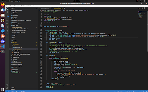
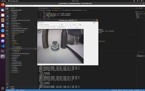
Following these steps, we found out the camera input is published as CompressedImage over the hostname/camera_node/input/compressed topic. We then follow ROS example code of publishing and subscribing to CompressedImage topic to write our own image topic, which consists of a subscriber that subscribes to the camera node and a publisher that republishes the images a few times every second. To verify the images are indeed published, we opened rqt_image_view and visually verified that the robot camera input is displayed in real-time on our custom topic.
Straight Line/ Rotation Task
The next goal is to test basic driving operations. First, we looked for topics to control the robot and to estimate its position through the number of ticks travelled by its wheels and found 'hostname/wheels_driver_node/wheels_cmd' as well as 'hostname/left(/right)_wheel_encoder_node/tick'. With the ticks data from the left and right wheels we can perform odometry through dead reckoning, which in this case is done by integrating the robot's position while it's moving each time it receives a message from either wheel:
def update_robot_pose(dl, dr): # dl and dr are the number of ticks advanced in the two wheels since the last update
<blockquote> distance = (dleft + dright) / 2
dtheta = (dright - dleft) / self.radius / 2
x += distance * math.cos(self.theta) # x unit is in ticks, need to be converted to meters later
y += distance * math.sin(self.theta)
theta += dtheta. </blockquote>
We keep track of the left and right wheel encoder ticks and compute the difference to get the change in wheel ticks, then compute the theta and update the robot position in the world frame. We script the robot to move 1.25 meters forward, and turn 90 degrees right four times. To turn the robot, we set the speed of each wheel to the same number with opposite signs.
Afterwards we measured the actual distance travelled, and saw if the turning angles were accurate. After tuning the parameters wheel_radius and meters_per_wheel_tick several times and measuring the wheel's radius physically with a ruler, we got relatively satisfactory results.
We moved on to the second part of the exercise.
First Step in the Second Part: Writing an LED Service Client
The way we will change the colour of the LED is by having a client container to send colour change requests to a server container which talks to the LED driver and carry out the change. After searching online we found the source code of GitHub dt-core/.../led_emitter_code.py. By reading the code, we know led_emitter_node can act as such a server, which receives ChangePattern requests and change the colour of the LED. We then added our client code to our script, which initializes a rospy.ServiceProxy object and we used it to send a ChangePattern request every time we want to change the colour.
Rosbag Recording
To reproduce any error we encounter, we record a rosbag of all the messages sent over the ROS message bus when the script is running. Following the manual, we used start_gui_tools and rosbag record -a to start recording the bag and ctrl+c to stop the recording. With the bag file obtained, we sent it from the start_gui_tools container to the duckiebot and then to our computers by two scp commands. On our own computer, we were able to start analyzing the information in the bag after installing the rosbag package for Python on our computers.
Driving around the Duckietown
As the final step, we scripted our robot to go around a square path and back to the original position, then go around in a circle and go back to the original position again, as well as indicate its progress of execution by the colour of the LED.
We broke down the tasks into subcommands:
- Turn the robot to target angle theta in the world frame.
- Move to x, y position in the world frame
- Change LED colour to red (state 1), white (state 2), blue (state 3) and green (state 4)
- Stop movement
To make the movement as accurate as we could, we used a simple PID controller during forward movement (with only the proportional term) to account for angle error resulting from inaccurate turning or drifting while driving between points. Combining everything, we started the program after starting the led_emitter_node container and the rosbag recording.
Analyzing the Rosbag
Following the duckietown manual section 'Working with Log', we were able to retrieve the messages in the bag file by iterating over the messages in the rosbag and filtering for the topics we look for. We used matplotlib to plot the location of the robot for each time step, and then used OpenCV to display the image at each step in the form of a video.
Part 1 Obstacles
- For part 1 image publisher, we first named our custom image topic hostname/MyCompressedImage but saw no image published in rqt_image_view(though rqt_image_view is able to display the topic name). After renaming the topic to HOST_NAME/compressed instead the issue is fixed and we start to receive the images.
- The robot seems to ignore some of the wheel commands when the program just boots up, so we decided to add some waiting at the start of the script before the robot starts moving to solve the issue.
- When reading the wheel encoder data, we were initially confused by the unit of measurement at first. We asked the TA and realized that the wheel encoder records data in ticks rather than in meters. However, even though we later converted one tick to 1/135 of a full circle, the robot still has significant error in estimating its distance travelled. After some investigation we found out its calibrated wheel radius is much smaller than the actual wheel radius measured with a ruler. Fixing the radius seemed to bring down the relative error within a few percentages.
Part 2 Obstacles
- We had the issue of the container not automatically shutting down, so we added the rospy.signal_shutdown call at the end of the script to make sure the program is properly shut down after the task.
- The biggest obstacle from this part comes from interpreting the wheel encoder data, as the messages published on the two topics have unreliable timestamps. Our first approach is to take the timestamp on the message as the true time when the sensor records the data and update the robot position as follows (assuming the last update is at time t0, and since then we received a message from the left wheel at time t1 and a message from the right wheel at time t2 with t2 > t1 > t0):
newleft = left_reading_at_t1
newright = last_right_reading + (right_reading_at_t2 - last_right_reading) * (t1 - t0) / (t2 - t0)
newtime = t1
dleft = newleft - last_left_reading
dright = newright - last_right_reading
update_robot_pose(dleft, dright)
t0 = newtime
However, we quickly found that the robot turned one way when it's driving forward. By analyzing the rosbag, we found that it was because while the messages from both wheels publish at about the same rates, the order got mixed up in the ROS message bus and timestamps on the messages seemed to only be applied after their order getting mixed up and was therefore unreliable as well.
We also noticed that despite the order being mixed up, the messages seem to be sent in a relatively constant rate, and both wheels sent about the same number of messages (930 vs. 940 in one of the test recordings) in the same time frame. This observation allowed us to use the following method to approximate the robot's position: We assume that a message from the left wheel is always paired up with a message from the right wheel at some point. Even though in theory the approximate can have larger errors as time goes if the two wheels desync, in testing this seemed to significantly improve the accuracy of driving.
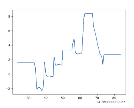
We also had some trouble plotting the data. When recalculating the robot pose from the wheel encoder data in the rosbag, we see the robot turns -4 radians at the start of the task which does not correspond to the 90 degrees turn we observed. We failed to recreate the same results that we see published on the pose2d topic. We believe that this could come from the difference in the messages received by our script and by the rosbag recording.

QAs
How do you convert the location and theta at the initial robot frame to the world frame?
The robot frame has both a rotation dtheta = pi / 2 and an offset dp = (0.32, 0.32). We can transformed the point Pr = (xr, yr, thetar) to world frame using:
xl = cos(dtheta)xr - sin(dtheta)yr + dpx
yl = sin(dtheta)xr + cos(dtheta)yr + dpy
thetal = thetar + dtheta
Can you explain why there is a difference between actual and desired location?
It could be our parameters are not tuned perfectly, and that the physical sensors are not perfectly accurate as well. Also at higher speed more of the odometry discrepancy may come from the momentum of the robot (as we assume the robot starts/stops instantly when the command is sent) or from slipping wheels in contact with the ground. For example, we found that the robot turns too fast when it's off the duckietown on the classroom floor, which could be that the classroom floor is more slippery.
Which topic(s) did you use to make the robot move? How did you figure out the topic that could make the motor move?
'wheels_cmd' for control and '...wheel_encoder_node/tick' for odometry. See the methods section for details.
Which speed are you using? What happens if you increase/decrease the speed?
Changing the robot speed seemed to make the turning angles inaccurate, since the turning angles parameter is tuned over only a fixed speed. For this reason we avoided changing the speed of our robot while carrying out the final task. We used 0.6 as our speed. If we went lower, the vehicle doesn’t move because of low motor output, and if we set a higher speed, we get a sharper, less accurate angle upon turning.
How did you keep track of the angle rotated?
See the pose update formulate in the methods section.
Which topic(s) did you use to make the robot rotate?
'wheels_cmd' for control and '...wheel_encoder_node/tick' for odometry. See the methods section for details.
How did you estimate/track the angles your DuckieBot has travelled?
See the pose update formulate in the methods section.
Print the total execution time for your entire task and the final location with respect to the world frame.
Final reading on the robot:
x = 0.018 y = -0.059
Execution time: 47.65644907951355 seconds
What is the final location of your robot as shown in your odometry reading? Is it close to your robot’s actual physical location in the mat world frame?
The final location of the robot according to the odometry readings is:
x = - 0.075 m, y = - 0.020 m
The actual physical location of the robot was x = 0.14 m and y= 0.05 m
It is close to its odometry location, which is about 0.20m from its actual location.


Link to Rosbag files: https://drive.google.com/file/d/1GrDDLPzS_YDMpu_xiDtxhWtvxZ5k1GNC/view?usp=share_link
References
ROS concepts (nodes, topics, services): http://wiki.ros.org/ROS/Concepts
Duckietown message and service types: https://github.com/duckietown/dt-ros-commons/tree/daffy/packages/duckietown_msgs
Message types in ROS std_msgs: http://wiki.ros.org/std_msgs
Sensor message types: http://wiki.ros.org/sensor_msgs
Publishing and Subscribing CompressedImage: http://wiki.ros.org/rospy_tutorials/Tutorials/WritingImagePublisherSubscriber
ROS template github repo: https://github.com/duckietown/template-ros
Duckietown manual on publishers and subscribers: https://docs.duckietown.org/daffy/duckietown-robotics-development/out/dt_infrastructure.html
Publisher naming issue: https://answers.ros.org/question/270881/unable-to-load-plugin-for-transport-image_transportcompressed_sub/
LED emitter node: https://github.com/duckietown/dt-core/blob/daffy/packages/led_emitter/src/led_emitter_node.py
Odometry with Wheel Encoder: https://docs.duckietown.org/daffy/duckietown-robotics-development/out/odometry_modeling.html
Rosbag reading and recording: https://docs.duckietown.org/daffy/duckietown-robotics-development/out/ros_logs.html
ROS tutorial on writing the client node: http://wiki.ros.org/ROS/Tutorials/WritingServiceClient%28python%29
Converting a pyplot plot to numpy array: https://stackoverflow.com/questions/7821518/matplotlib-save-plot-to-numpy-array
Cheat sheet google doc: https://docs.google.com/document/d/1bQfkR_tmwctFozEZlZkmojBZHkegscJPJVuw-IEXwI4/edit